Building a mini-case for a small server
Discontinued since 2006
Earlier Update: 200mhz was really not enough, customized the board for a AMD K6-II 450MHz cpu
It's my first try building/modifying a case. I had an old Baby-AT Board by VIA and a 200mhz cpu sitting on it, it's a real small board (21.5cm x 23.5cm). So I came to the Idea I could build a small box for it and use it as a little server, or box to experiment with (different Linux/GNU distros). It also shouldn't produce too much noise, so a passive cooled cpu and a heat regulated power supply would be good. And of course, the case shouldn't look too bad.
- Gathering Components
- Building the Case Step 1
- Building the Case Step 2
- A Section about the PC Hardware
- Finishing it?
1. Gathering Components
I first looked what I have:
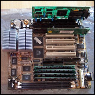
No Pentium MMX 200MHz like before. Now an AMD K6-II 450MHz will be used, with the cooling block of an AMD Athlon XP cooler, the Baby-AT board, an ISA graphics card and a PCI network card:
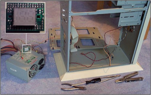
A really big big-tower that we still had, I already pulled out the power supply, which is heat regulated - good for a low noise machine. A segment display, which can do "199" at the highest was also in it, but I came to the decision that I won't use it:
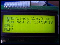
I rather used a 4x20 display - works with LCDproc over parallelport:
Other Stuff which I also had was:
- A damaged mainboard where I could get the onboard pc-speaker from
- The Cover for the High Tower which I could use for a case
- A Wooden Board
- The only thing which I bought was Dupli-Color Zapon spray (quick drying acrylic clear lacquer - you'll see for what it is used, later
- Different Tools of course
2. Building the Case Step 1
I didn't had a real plan for doing this, I..
- ..sawed Wooden Boards, getting Holes etc. into them
- ..sawed the metal cover of the big-tower into a form which will get part of this case then
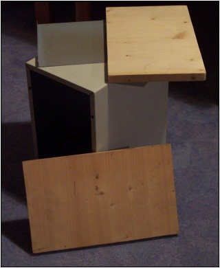
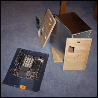
Here's a Picture of it, I first thought I'd use the metal sheet for the bottom of the case, but I didn't do in the end:
3. Building the Case Step 2
After that I..
- ..drilled holes in the metal for holding a board, and a hd
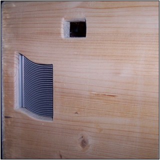
- ..drilled holes in the wood for the power supply and for connecting wood and metal, saw other openings in the wood, too (for example for the passive cooler of the cpu, seen below)
- ..sawed another wooden board for the bottom, because it wasn't good to use the single metal sheet for that
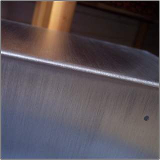
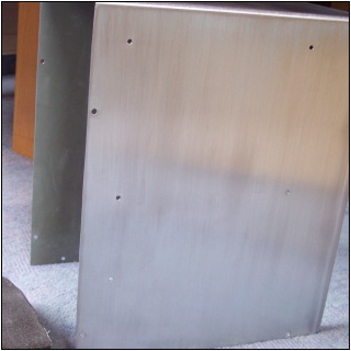
- ..drilled more holes in the metal and "brushed" it - in reality I just used sandpaper for this, but it looks brushed metal like
Here are some pics of it:
4. A Section about the PC Hardware
Sadly I didn't continue this project for a long time (the last thing I did was taking the photo of the lcd at 21th November 2004)
Now it moves on!
I have another older CPU, AMD K6-II 450MHz. One of the points that I didn't really continue was also the nonsense I saw in it.. Now if this CPU could work, the box could be used as an Internet Browser and Chat or Instant Messenger PC (or something like that). So the voltage needed to be changed, otherwise it was really too much (2.8V compared to the 2.2V needed), now it is at 2.3V so if I could somehow overclock it slightly, that will be good - but I am probably just able to have it underclocked, and so might regulate the voltage down to 2.0 or 2.1V then. The problem is the multiplier: You can't simply change it. I might compare the amd cpus datasheets to find out.
How the voltage was changed:
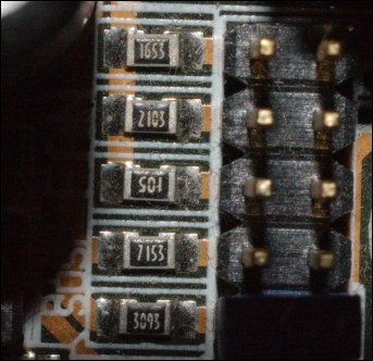
- I found out that near each pin on the board, which stands for a voltage, there is one resistor near it, I took a photo so you could easier look on them.
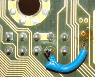
- I put two pieces of small wire in 2 pins of the cpu socket, according to the specs of it (one pin "Vcc2" for Core Voltage and "Vss" for Ground, to check IO Voltage Vcc3 and Vss is used)
- Then I checked at them with a Voltmeter if everything is as expected. It was! Every jumper changed the voltage like it should do.
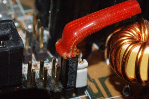
- Now we could try changing the resistors and differ the jumper settings, or trying more than one jumper. Nothing did result in 2.2V. So one of the resistors was bridged and added a potentiometer to regulate for the best voltage.
- After getting the wanted voltage, you can measure the resistance of the potentiometer and add a normal resistor. So it is at 2.3V now! This is the added resistor under a hose:
5. Finishing it
Coming soon ! You'll soon see how I finish the metal cover with sandpapering it a bit more (it's not clean enough), using the acrylic clear lacque spray, and putting it alltogether - after that a new section is going to open where everything is going to be described about the software installation. To be realistic: I will probably never finish this, the hardware ist just too old, slow and energy consuming (greenpeace would tell it "not green enough"). But I hope at least this part might have helped you for something...


